 Freelance
Traveller
Freelance
Traveller
Sometimes I hear people say on the internet how they wish there was a manual or outline of instructions on how to draw Traveller deckplans. Some of these people have Campaign Cartographer 2 Pro, the software I use. I decided to compose a short essay on one of the methods I use to create Traveller deckplans. I am not claiming that this method is the best or the easiest to use, it's the one I use most often. I make no guarantee that this method will transform you into an expert at creating Traveller deckplans, I just hope it helps.
Read the CC2Pro Users Manual first, before starting CC2Pro. The first time you load CC2Pro follow the interactive user's guide. Doing these two things before you begin this outline will help you understand how CC2Pro works.
-
Setup (Approx. 1 hr.)
-
Open CC2 and load the Blank Dungeon template. Click 'Save as' from file menu, open the Other folder and save the new template as 'Blank starship'. Close the Blank Dungeon template and open the Blank Starship template you just created.
-
Now left-click the Layers Menu in the Status Bar at the top (L:Background) to get the Select Layer box listing all of the layers in CC2. We are going to rename several. Here's a list of the layers we will use: a) Border, b) Bulkheads, c) Colors, d) Doors, Hatches, Iris Valves, e) Drives, f) Furniture, g) Hex/Square Grid, h) Interior Walls, i) Labels, j) Merge, k) Referee, l) Standard, m) Sub-Craft 1, n) Sub-Craft 2, o) Symbol, p) Symbol Definition, q) User 1, and r) User 2. Those in bold print already exist so you wont have to create or rename layers for them. Delete any left over layers such as traps, wall fixtures, etc. Click OK in the Select Layer box to save the new names.
-
We will now create the square grid for the background. Left click the first small box of the Hex/Square Grid layer (a check appears and the layer name has a gray highlight) to select that layer. Activate snap by left-clicking on the snap button at the bottom of the screen. Select a color like the light blue in the left color sidebar. Right-click on the hex/square gird in the left side bar. Type " 5' " in the Command Prompt to set the grid to a 5 foot (or approximately a 1.5m). Hit the enter button on the keyboard to set the origin of the grid at 0,0. Stretch the grid to 70' (top/bottom) by 90' (left/right) mark (or thereabouts). Left-click on the Zoom Extents box in the right sidebar to zoom in on the work area. Save as "Blank Starship" template.
-
-
Create Symbols (Approx. 1 hr.)
-
Left click on the black square in the Color Bar of the left. Change the Layer to Symbol Definition. Left click the open catalog button in the Symbol Catalog Window and load the Blank Dungeon.FSC. Click on the fill style (FS: Solid) and change it to hollow. Click on the line style (LS: Solid) and create a new line style named dotted with a pattern length of 1/16". We will create eight basic symbols. The names of the symbols will be a) Iris, Down, b) Iris, Up, c) Iris, Up/Down, d) Hatch, Up, f) Hatch, Down, g) Hatch, Up/Down, h) Iris, wall, and i) Hatch, wall.
-
Left click on the Symbols menu in the menu bar, then left click on the Symbol Manager in the list. Click on the new button to create a symbol creation window. Name the symbol Iris, Down. Left click on two spots in the View Window to open the Symbol creation window. Move the scroll bars to the left and bottom to find the origin at 0,0. Make sure you have the line style reset to solid and the fill style is set to hollow. Left click on the circle in the draw toolbar on the right side of the screen. Turn snap on. Click the origin to set the center of the circle. Turn snap off. Click on a spot 1' 6" from the center to set the point on the circle. Close the symbol creation window and save it.
-
Left click on the Symbols menu in the menu bar, then left click on the Symbol Manager in the list. Left click on the Iris, Down symbol you just created and clone it one time with the name Iris, Up/Down. Select the Iris, Up/Down symbol you just cloned and edit it. Reset the line style to dotted. Left click on the circle in the draw toolbar on the right side of the screen. Turn snap on. Click the origin to set the center of the circle. Turn snap off. Click on a spot 1' 3" from the center to set the point on the circle. Close the symbol creation window and save it.
-
Left click on the Symbols menu in the menu bar, then left click on the Symbol Manager in the list. Left click on the Iris, Down symbol you created and clone it one time with the name Iris, Up. Select the Iris, Up symbol you just cloned and edit it. Left click on the Change Line Style command in the Edit Toolbar, select the solid line and change it to a dotted line. Close the window and save the new symbol.
-
Open the Symbol Manager again and clone each of the three symbols just made replacing the word Iris with Hatch. Move the new cloned Hatch symbols together below the Iris symbols.
-
We will add the hatch hinge and operation wheel to each of the Hatch symbols. Select the Hatch, Down and click edit from the Symbol Manager. Make sure you have the line style reset to solid and the fill style is set to hollow. Left click on the circle in the draw toolbar on the right side of the screen. Turn snap on. Click the origin to set the center of the circle. Turn snap off. Click on a spot 6" from the center to set the point on the circle. Turn snap back on. Left click on the Line button in the draw Toolbar on the left. Left click on the center of the circle for the first point of the line and then click on a snap 1' to the left/right. Right click to stop line command. Left click to repeat the line command. Left click on the center of the circle for the first point of the line and then click on a snap 1' to the up/down. Right click to stop line command. Turn snap off and turn Ortho on. Left click on the Move command in the Edit Toolbar. Move the horizontal line horizontally until it is centered in the small circle then move the vertical line vertically until it is centered also. Reset the fill style to solid. Turn Ortho off and turn Snap on. Left click on the Box button in the Draw Toolbar on the left. Left click at the center of the circles (origin) for the first point. Turn off snap. Move the cursor 1' 6" to the right and 3" up, left click to finish the box. Use the move command from the Edit Toolbar and reposition the hinge to a location covering the bottom of the circle. Close the window and save the symbol.
-
Repeat step 6 editing the Hatch, Up/Down and the Hatch, Up symbols.
-
Left click on the Symbols menu in the menu bar, then left click on the Symbol Manager in the list. Click new and create Iris, wall. Left click on the Polygon in the Draw Toolbar on the right. Turn on snap. Click the origin (0,0) to start the triangle base, move horizontally 1' to the right and click again to set the other end of the base. Move the cursor up 2' and make the last click forming a right triangle. Turn snap off and turn Ortho on. Left click on the Node Edit in the Edit Toolbar on the right. Select the apex (top) node of the triangle and move it 6" to the left. Right click to stop the command. Select the apex (top) node of the triangle and move it 6" to the down. Turn off Ortho. Left click on the Move command in the Edit Toolbar and select the triangle. Move it until the extreme apex (top) of triangle is positioned over the origin (0,0). Left click the Copy in the Edit Toolbar, select the triangle and rotate the copied triangle (depressing the shift key) until the two triangles are 180 degrees opposite of each other. Close the symbol window and save the Iris, wall symbol.
-
Open the Symbol Manager and create a new symbol named Hatch, wall. Left click the line width (W:0) in the status bar at the top and change the line width to 3". Turn snap on. Select the Line command from the Draw Toolbar on the right. Draw a vertical line 3' long. Turn snap off and turn Ortho on. Select the move command and move the line 6" up. Turn Snap on and Ortho off. Left click on the Line command in the draw Toolbar. Draw a horizontal line 1' long above the vertical line then draw another 1' long horizontal line below the vertical line. Change the line width to 2". Select the Line command and draw a 1' long vertical line to the right and one to the left of the vertical 3' line. Draw a 1' long horizontal line to the left of the 3' vertical line. Use the Move command from the Edit Toolbar and reposition the 3" wide horizontal lines to the ends of the 3" wide, 3' long vertical line. Using the Move command reposition the horizontal 2" wide line to the center of the 3" wide, 3' long vertical line. Move the 2" wide vertical lines to the ends of the 2" wide horizontal line in the center of the 3' vertical line. Once you have repositioned the lines the symbol should look like a serif capital "I" with a smaller capital "H" in the center. Close the symbol window and save.
-
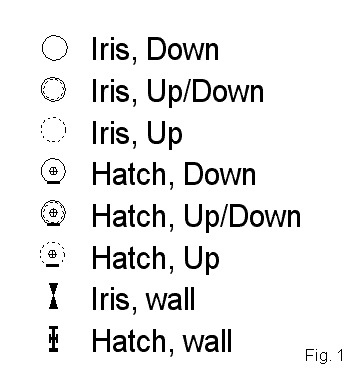 Open
the Symbol Manager and check to see that there are eight symbols listed.
(See Fig. 1) Click the Save as Catalog and save the new catalog in the Symbols
folder as "BasicStarshipSymbols". Close the Symbol Manager. To load the
new symbols left click on the Open Folder in the Symbol Catalog Window on
the left. Select "BasicStarshipSymbols" and open it. Left click on the Layers
in the Status Bar at the top. The Select Layer box opens. Left click the
small third box in the Hex/square grid line (an F appears) freezing that
layer. Left click the first small box of the Bulkheads layer ( a check appears
and the layer name has a gray highlight). Click Ok. Save the template as
"Blank Starship" in the template folder.
Open
the Symbol Manager and check to see that there are eight symbols listed.
(See Fig. 1) Click the Save as Catalog and save the new catalog in the Symbols
folder as "BasicStarshipSymbols". Close the Symbol Manager. To load the
new symbols left click on the Open Folder in the Symbol Catalog Window on
the left. Select "BasicStarshipSymbols" and open it. Left click on the Layers
in the Status Bar at the top. The Select Layer box opens. Left click the
small third box in the Hex/square grid line (an F appears) freezing that
layer. Left click the first small box of the Bulkheads layer ( a check appears
and the layer name has a gray highlight). Click Ok. Save the template as
"Blank Starship" in the template folder.
-
-
Mathematics (Time Varies)
Use mathematics to determine the volume of the ship to be drawn including a breakdown of the component volumes. A useful website with the various volume formulas can be found at http://mathworld.wolfram.com/topics/SolidGeometry.html. The component volumes can be determined from the design sequence. As the example I will use a 100 dton Scout Ship. Here is the volume breakdown:
Item dTons Comments Bridge 20 About 50% for control room, 25% for avionics, 25% for airlock, ship's locker, other Computer 1 Model 1/bis Jump Drive 3 Jump 2 Maneuver Drive 8 3G, Agility 3 (w/o energy weapons) Power Plant 9 3 EP Fuel 45.25 Fuel for two Jump-2 and seven weeks maneuver Weaponry 1.5 0.5 dTons for an autoloader and a 6 round missile magazine adjacent to turret Craft 4 Air/raft Staterooms 8 Required crew: 1. Additional stateroom for mission specialist. Cargo 0.25 Storage for maintenance robot Each dTon is fourteen cubic meters. The volumes in cubic meters and the corresponding floor space (assuming 3m (10') between decks) in square feet are given below. The length x width column gives an approximation of the dimensions. If there is more than one set of dimensions then that item has been subdivided in order to reflect subdivisions of that item.
Item m3 feet2 length x width (Comments) Bridge 140 502.0 15'x17',5'x10',5'x5'
(Control Room, Airlock, Ship's Locker)Computer 14 50.2 5'x10' Jump Drive 42 150.6 15'x10' Maneuver Drive 112 401.6 20'x20' Power Plant 126 451.8 21'x22' Fuel 591.5 2121.1 (Used as fill) Weaponry 21 75.3 8'x9' Craft 56 200.8 10'x20' Staterooms 112 401.6 10'x10', 10'x10', 20'x10'
(2xStaterooms, Crew Lounge)Now that we have the components in a usable format we can begin the actual drawing.
-
Drawing (Time varies depending on ship size / complexity and architect experience.)
There are many approaches to drawing deckplans. There are no formal names to them. The method presented will start from the inside of the ship, the habitation space, and then work out to the exterior hull of the ship. You should save your work every few steps with a differing numeric designator at the end of the ship name (ex. FreeTrader1, FreeTrader4). In case you make a serious mistake you wont have to restart from the beginning.
-
Load the "Blank Starship" template. Now click the 'Save As' from the File menu and save your work as "ScoutshipOne" into a new folder to hold your starship deckplans. Check to make sure that the color is black, the line width is set to 0 (zero), line style is solid and fill style is hollow. Make sure that the hex/square grid in the Select Layers box is frozen and set the active layer (by clicking the first box) to Border. Click the Zoom Out once from the Views toolbar on the right then click the Zoom Window. To set the zoom window click first to the left and below the origin point (0,0) then click a point about 30' to the right and 30' above the square grid.
-
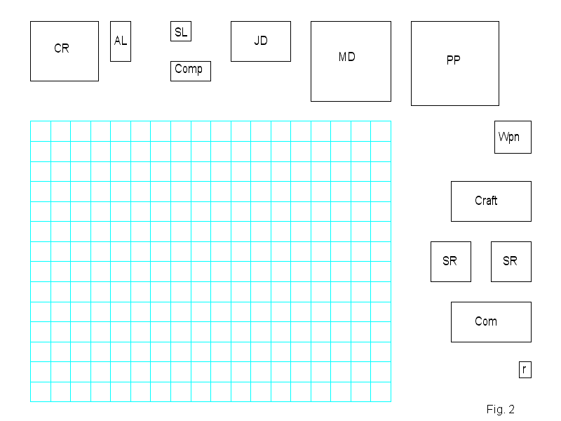
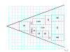
 Using
the line command from the Draw Toolbar create boxes as given in the l x
w column in the area outside of the square grid. Left click on the Text
Specs and change the text height to 2' 6", close the Text Properties box.
Left click the Text button from the Draw Toolbar and using abbreviations
give each of the boxed an id label. (See Fig 2) (click on the figure at
right to see it full size, 800x600)
Using
the line command from the Draw Toolbar create boxes as given in the l x
w column in the area outside of the square grid. Left click on the Text
Specs and change the text height to 2' 6", close the Text Properties box.
Left click the Text button from the Draw Toolbar and using abbreviations
give each of the boxed an id label. (See Fig 2) (click on the figure at
right to see it full size, 800x600) - Using the Change Layers from the Edit Toolbar change the layer of every fourth 'box' to Referee. Repeat this, picking different boxes and change their layer to User 1. Repeat again changing the layer of the selected boxes to User 2. The boxes should be on four different layers.
-
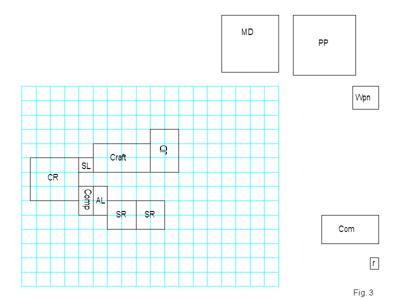
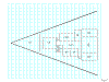
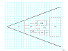
 Starting
with the Control Room (15x17) and using the Move command from the Edit Toolbar
move the various boxes into the general shape of the ship depending on the
configuration (triangle/wedge in this case). Some of the boxes might have
to be rotated by depressing the Shift key before final placement. (See Fig
3) (click on the figure at right to see it full size, 800x600)
Starting
with the Control Room (15x17) and using the Move command from the Edit Toolbar
move the various boxes into the general shape of the ship depending on the
configuration (triangle/wedge in this case). Some of the boxes might have
to be rotated by depressing the Shift key before final placement. (See Fig
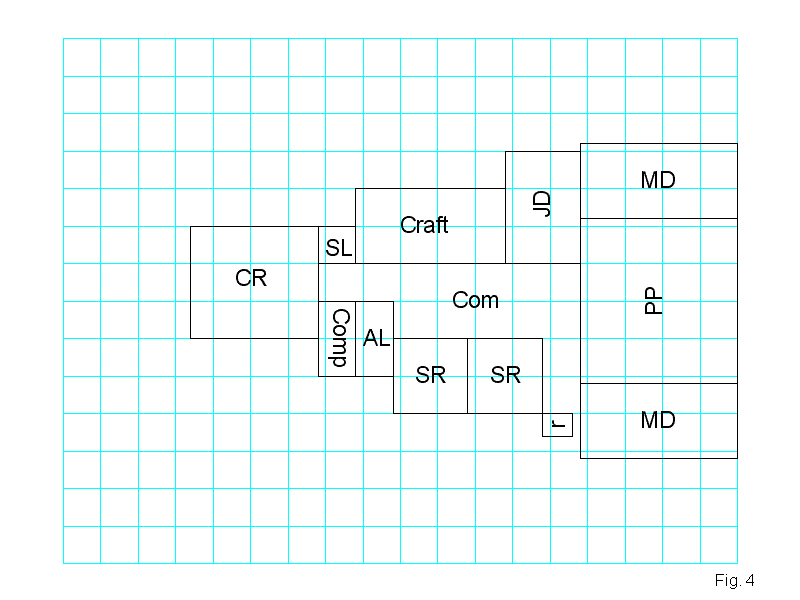
3) (click on the figure at right to see it full size, 800x600)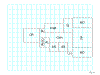 After
moving the power plant I decided to break the maneuver drive into two units
and placed them to either side of the power plant. I have decided that the
weaponry box will occupy a space above the main deck and have moved the
common label to the central open area. The boxes still outside of the grid
have been erased. Use the Zoom Extents command from the View Toolbar to
zoom back in. Then the drawing has been moved to the right until the maneuver
drives lie next to the edge of the grid on the right. (See Fig 4) (click
on the figure to see it at full size, 800x600)
After
moving the power plant I decided to break the maneuver drive into two units
and placed them to either side of the power plant. I have decided that the
weaponry box will occupy a space above the main deck and have moved the
common label to the central open area. The boxes still outside of the grid
have been erased. Use the Zoom Extents command from the View Toolbar to
zoom back in. Then the drawing has been moved to the right until the maneuver
drives lie next to the edge of the grid on the right. (See Fig 4) (click
on the figure to see it at full size, 800x600) -
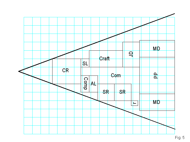
 Change
the active layer by left clicking on the Layers in the Status Bar and clicking
the first box of the Bulkheads layer. Click the third box, freezing the
Border, Referee, User 1, and User 2 layers. Change the fill style to solid
and the line width to 6". To get the outside hull in a shape corresponding
to the general layout of the interior use the Line command from the Draw
Toolbar and start the line at the bottom left corner of the control room
box then click at the bottom left corner of the leftmost stateroom. Left
click on the Edit in the File Toolbar at the top, go to Reshape and select
the Mirror command. Select the 6" wide line just drawn as the entity to
mirror. Left click on the bottom left corner and the bottom right corner
of the control room box to set the Mirror axis line. Use the Move command
to move the new line until just touches the top left corner of the box for
the control room. Left click on the Trim command in the Edit Single Entities
Toolbar on the left. Select the one 6" wide hull lines, click do it, then
set the trim edge by clicking on the right edge of the grid. Repeat for
the other hull line. Using the Trim to Intersect command from the Edit Single
Entities Toolbar select the two 6" outer hull lines to trim. The lines should
extend to intersect to a point to the left of the control room. (See Fig
5) (click on the figure to see it full size, 800x600)
Change
the active layer by left clicking on the Layers in the Status Bar and clicking
the first box of the Bulkheads layer. Click the third box, freezing the
Border, Referee, User 1, and User 2 layers. Change the fill style to solid
and the line width to 6". To get the outside hull in a shape corresponding
to the general layout of the interior use the Line command from the Draw
Toolbar and start the line at the bottom left corner of the control room
box then click at the bottom left corner of the leftmost stateroom. Left
click on the Edit in the File Toolbar at the top, go to Reshape and select
the Mirror command. Select the 6" wide line just drawn as the entity to
mirror. Left click on the bottom left corner and the bottom right corner
of the control room box to set the Mirror axis line. Use the Move command
to move the new line until just touches the top left corner of the box for
the control room. Left click on the Trim command in the Edit Single Entities
Toolbar on the left. Select the one 6" wide hull lines, click do it, then
set the trim edge by clicking on the right edge of the grid. Repeat for
the other hull line. Using the Trim to Intersect command from the Edit Single
Entities Toolbar select the two 6" outer hull lines to trim. The lines should
extend to intersect to a point to the left of the control room. (See Fig
5) (click on the figure to see it full size, 800x600) -
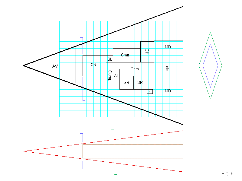
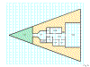
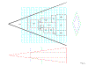 At
this point it is time to do a check of the volume of the ship as drawn.
In essence the wedge configuration is a pyramid. The volume of a pyramid
is: V=1/3(Ah) where A = the base area and h = the height. After doing the
calculations it appears that with a hull length of 94' the volume is too
small at 64 dtons. After some trial and error, moving the outer hull forward
22' the volume is much closer. With the hull 116' long the volume is 100.9
dtons, acceptable. Drawing (on an unused layer) a side view cutaway (the
red outline below the deckplans) allows me to check to make sure that the
habitation deck has enough headroom space. Looking at the cutaway two questions
arise about the overhead clearance at the front of the control room and
the craft bay. Drawing two diamond cross-sections (green and blue) at the
rear of the deckplan this can be verified to be acceptable if the components
are moved toward the rear by 1'. Using the formula above I also calculated
the space needed for three of the five tons of avionics and place a line
and label for such on the Borders layer. (See Fig 6) (click on the figure
to see it at full size, 800x600)
At
this point it is time to do a check of the volume of the ship as drawn.
In essence the wedge configuration is a pyramid. The volume of a pyramid
is: V=1/3(Ah) where A = the base area and h = the height. After doing the
calculations it appears that with a hull length of 94' the volume is too
small at 64 dtons. After some trial and error, moving the outer hull forward
22' the volume is much closer. With the hull 116' long the volume is 100.9
dtons, acceptable. Drawing (on an unused layer) a side view cutaway (the
red outline below the deckplans) allows me to check to make sure that the
habitation deck has enough headroom space. Looking at the cutaway two questions
arise about the overhead clearance at the front of the control room and
the craft bay. Drawing two diamond cross-sections (green and blue) at the
rear of the deckplan this can be verified to be acceptable if the components
are moved toward the rear by 1'. Using the formula above I also calculated
the space needed for three of the five tons of avionics and place a line
and label for such on the Borders layer. (See Fig 6) (click on the figure
to see it at full size, 800x600) -
 Erase
the side view cutaway and the diamond cross-sections. Use the Zoom Extents
to zoom in. The drawing has extended beyond the original grid. Unfreeze
all of the layers, except the hex/square grid layer. Using the Move command
at a point to the left and above the drawing, left click and hold the click
down and drag a selection window across to a point at the bottom right which
covers the drawing. Release the left click. Move the drawing until the forward
point of the hull is 4' inside the leftmost, zero line, grid and the lower
part of the outer hull is about 4' above the zero line of the grid at the
bottom. Freeze the Border, Bulkheads, Referee, User 1 and User 2 layers.
Unfreeze the hex/square grid. Erase the old grid. Select the light blue
color again. Right click on the Hex Grid button in the Overland Toolbar
at the top left of the screen, highlight square. Set the grid to 5' and
the start of the grid at 0,0. Stretch the grid until it covers the drawing.
Use the Send to Back command from the Entity Order Toolbar on the right,
select the grid and 'submerge' it. Click redraw from the View in the File
Toolbar at the top. Select the black color. (See Fig 7) (click on the figure
to see it at full size, 800x600)
Erase
the side view cutaway and the diamond cross-sections. Use the Zoom Extents
to zoom in. The drawing has extended beyond the original grid. Unfreeze
all of the layers, except the hex/square grid layer. Using the Move command
at a point to the left and above the drawing, left click and hold the click
down and drag a selection window across to a point at the bottom right which
covers the drawing. Release the left click. Move the drawing until the forward
point of the hull is 4' inside the leftmost, zero line, grid and the lower
part of the outer hull is about 4' above the zero line of the grid at the
bottom. Freeze the Border, Bulkheads, Referee, User 1 and User 2 layers.
Unfreeze the hex/square grid. Erase the old grid. Select the light blue
color again. Right click on the Hex Grid button in the Overland Toolbar
at the top left of the screen, highlight square. Set the grid to 5' and
the start of the grid at 0,0. Stretch the grid until it covers the drawing.
Use the Send to Back command from the Entity Order Toolbar on the right,
select the grid and 'submerge' it. Click redraw from the View in the File
Toolbar at the top. Select the black color. (See Fig 7) (click on the figure
to see it at full size, 800x600) -
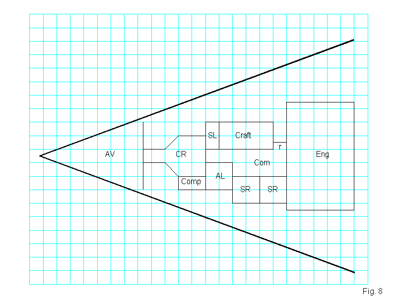
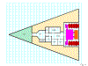
 Looking
over the layout there are a few changes to be made. In order have a single
engineering space I have decided to combine all of the drives tonnage together.
A total area for the drives is 1004 square feet. Since 25' by 40' is 1000'
square feet I will use that as my engineering space. (The actual drives
will be drawn in later.) Freeze the Bulkheads layer and unfreeze the Border,
Referee, User 1 and User 2 layers. Move the 3' x 4' robot area away from
the rear of the ship. Erase the JD, MD, and PP labels and box outlines.
Draw a 25' by 40' engineering box at the rear of the ship. Using the Move
command, reposition it until it is centered in the rear of the ship. Place
the label Eng in the box. Select the other boxes (Control Room, staterooms,
craft, etc.) and move them 1' toward the rear. Erase the line between comp
and AL and erase the Comp label. Move the AL label until it is centered
in the 10' x 10' just created. Draw two lines enclosing an 5' x 10' area
beneath the Control Room box and label it Comp. Erase the top line of the
SL box and draw lines to change the area to 5' x 10'. Trim the top and bottom
line of the Control Room until it is 15' long from the rear of the back
line of the Control Room. Erase the forward line of the Control Room. Draw
two 45 degree lines from the top line and the bottom line covering one 5'
square each. Draw two more lines from the ones just drawn to the line of
the Avionics section. The Control Room should now be shaped like a funnel.
Draw a line from the bottom of the craft box to the Engineering box. Move
that line up 2.5'. Place the "r" label in the small alcove. Erase the old
robot box. Select all of the labels and use the Change Layer command to
change them to the Labels layer, then freeze it. Select all of the lines
between the outer hull lines and change their layer to User 2, then freeze
it. (See Fig 8) (click on the figure to see it at full size, 800x600)
Looking
over the layout there are a few changes to be made. In order have a single
engineering space I have decided to combine all of the drives tonnage together.
A total area for the drives is 1004 square feet. Since 25' by 40' is 1000'
square feet I will use that as my engineering space. (The actual drives
will be drawn in later.) Freeze the Bulkheads layer and unfreeze the Border,
Referee, User 1 and User 2 layers. Move the 3' x 4' robot area away from
the rear of the ship. Erase the JD, MD, and PP labels and box outlines.
Draw a 25' by 40' engineering box at the rear of the ship. Using the Move
command, reposition it until it is centered in the rear of the ship. Place
the label Eng in the box. Select the other boxes (Control Room, staterooms,
craft, etc.) and move them 1' toward the rear. Erase the line between comp
and AL and erase the Comp label. Move the AL label until it is centered
in the 10' x 10' just created. Draw two lines enclosing an 5' x 10' area
beneath the Control Room box and label it Comp. Erase the top line of the
SL box and draw lines to change the area to 5' x 10'. Trim the top and bottom
line of the Control Room until it is 15' long from the rear of the back
line of the Control Room. Erase the forward line of the Control Room. Draw
two 45 degree lines from the top line and the bottom line covering one 5'
square each. Draw two more lines from the ones just drawn to the line of
the Avionics section. The Control Room should now be shaped like a funnel.
Draw a line from the bottom of the craft box to the Engineering box. Move
that line up 2.5'. Place the "r" label in the small alcove. Erase the old
robot box. Select all of the labels and use the Change Layer command to
change them to the Labels layer, then freeze it. Select all of the lines
between the outer hull lines and change their layer to User 2, then freeze
it. (See Fig 8) (click on the figure to see it at full size, 800x600) -
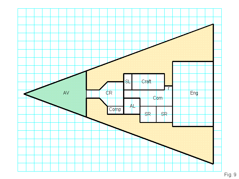
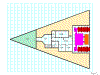
Now to add a little color to the drawing. Check to see that the Bulkheads, Hex/Square Grid, Labels and User 2 layers are frozen. Click the second box of the Hex/Square Grid to hide it. Turn snap off. Change the fill style to solid. Select the yellowish-tan color (about 1/3 down in the Color Bar). As you proceed with the next command some of the lines forming the boxes of the interior components will disappear. When the Colors layer is 'sent behind' later they should reappear. Use the Zoom Window and zoom in on the area above the boxes and below the outer hull line. Left click the Polygon command from the Draw Toolbar. Left click where the avionics line intersects with the outer hull line, move the cursor down to where the avionics wall intersects with the Control Room wall, left click to set the point of the polygon, move the cursor around the rest of the control room, left clicking where the lines change direction, following the upper lines of the boxes until you get to the rear of the ship, left clicking at the rear line the engineering section, then proceed to the outer hull line for a final left click. Right click once to set the polygon. Repeat this same procedure for the space below the boxes and bottom hull line. Select the light green color, use the Polygon command and make a triangle around the edge of the avionics section. Left click the Send Behind command from the Order Entities Toolbar, select the three polygons just made and 'submerge' them. Click Redraw from the View menu.
-
 Select
the black color. Change the line width to 6". From the Select Layers box,
freeze the Colors layer and make the Bulkheads layer active. Using the Line
command from the Draw Toolbar draw lines encompassing the Control Room and
Computer. Draw lines around the Engineering, Craft, and Airlock boxes. Draw
lines separating the Avionics from the fuel (yellow-tan color) and more
lines separating the habitation areas from the fuel not already covered.
Change the line width to 3". Change the active layer to Interior Walls and
freeze the Bulkheads layer. Use the Zoom Window command from the View Toolbar
and zoom in to the area just outside the habitation space of the ship. Using
the Line command draw the interior walls separating the staterooms from
each other and the common area, separating the ship's locker from the hallway
and separating the avionics section from the control room. Click Zoom Extents.
(See Fig 9) (click on the figure to see it at full size, 800x600)
Select
the black color. Change the line width to 6". From the Select Layers box,
freeze the Colors layer and make the Bulkheads layer active. Using the Line
command from the Draw Toolbar draw lines encompassing the Control Room and
Computer. Draw lines around the Engineering, Craft, and Airlock boxes. Draw
lines separating the Avionics from the fuel (yellow-tan color) and more
lines separating the habitation areas from the fuel not already covered.
Change the line width to 3". Change the active layer to Interior Walls and
freeze the Bulkheads layer. Use the Zoom Window command from the View Toolbar
and zoom in to the area just outside the habitation space of the ship. Using
the Line command draw the interior walls separating the staterooms from
each other and the common area, separating the ship's locker from the hallway
and separating the avionics section from the control room. Click Zoom Extents.
(See Fig 9) (click on the figure to see it at full size, 800x600) -
 Use
the Zoom Window command and zoom in to an area around the habitation space.
Turn snap on. Left click on the Break command in the Edit Single Entities
Toolbar on the left. Select the interior wall line separating the ship's
locker from the hallway. Left click 1' from the each end of the 3" wide
interior wall line and create a 3' wide doorway. Repeat this creating a
doorway between each of the staterooms and the common area. (The thin lines
of the boxes saved on the User 2 layer will still be visible and will act
as a guide when actually placing the doors later.) Change the active layer
to Bulkheads and freeze the Interior Walls layer. Use the Break command
and create doorways between the control room and hallway, the airlock and
hallway, the craft bay and common area, finally between the engineering
and common area. (See Fig 10) (click on the figure to see it at full size,
800x600)
Use
the Zoom Window command and zoom in to an area around the habitation space.
Turn snap on. Left click on the Break command in the Edit Single Entities
Toolbar on the left. Select the interior wall line separating the ship's
locker from the hallway. Left click 1' from the each end of the 3" wide
interior wall line and create a 3' wide doorway. Repeat this creating a
doorway between each of the staterooms and the common area. (The thin lines
of the boxes saved on the User 2 layer will still be visible and will act
as a guide when actually placing the doors later.) Change the active layer
to Bulkheads and freeze the Interior Walls layer. Use the Break command
and create doorways between the control room and hallway, the airlock and
hallway, the craft bay and common area, finally between the engineering
and common area. (See Fig 10) (click on the figure to see it at full size,
800x600) -
 Most
deckplan architects consider 50% to 75% of the floor space of the various
drives to be the actual mechanisms. Change the active layer to Drives and
freeze the Bulkheads layer. Once the actual drive mechanism space has been
determined use the Draw commands (in three different colors) to create the
drive mechanisms outside of the hull of the ship. Use the Move command to
then place the drives in the Engineering section (you will overdraw the
label but it will be brought to the front later). (After placing my drives
I froze the drives layer and reopened the Bulkheads layer and used the Break
command to create two small gaps in the rear outer hull, close to the corners
of the Engineering section. This is my engineering maintenance hatch which
can only be opened from the inside of the ship during overhaul maintenance.)
(See Fig 11) (click on the figure to see it at full size, 800x600)
Most
deckplan architects consider 50% to 75% of the floor space of the various
drives to be the actual mechanisms. Change the active layer to Drives and
freeze the Bulkheads layer. Once the actual drive mechanism space has been
determined use the Draw commands (in three different colors) to create the
drive mechanisms outside of the hull of the ship. Use the Move command to
then place the drives in the Engineering section (you will overdraw the
label but it will be brought to the front later). (After placing my drives
I froze the drives layer and reopened the Bulkheads layer and used the Break
command to create two small gaps in the rear outer hull, close to the corners
of the Engineering section. This is my engineering maintenance hatch which
can only be opened from the inside of the ship during overhaul maintenance.)
(See Fig 11) (click on the figure to see it at full size, 800x600) -
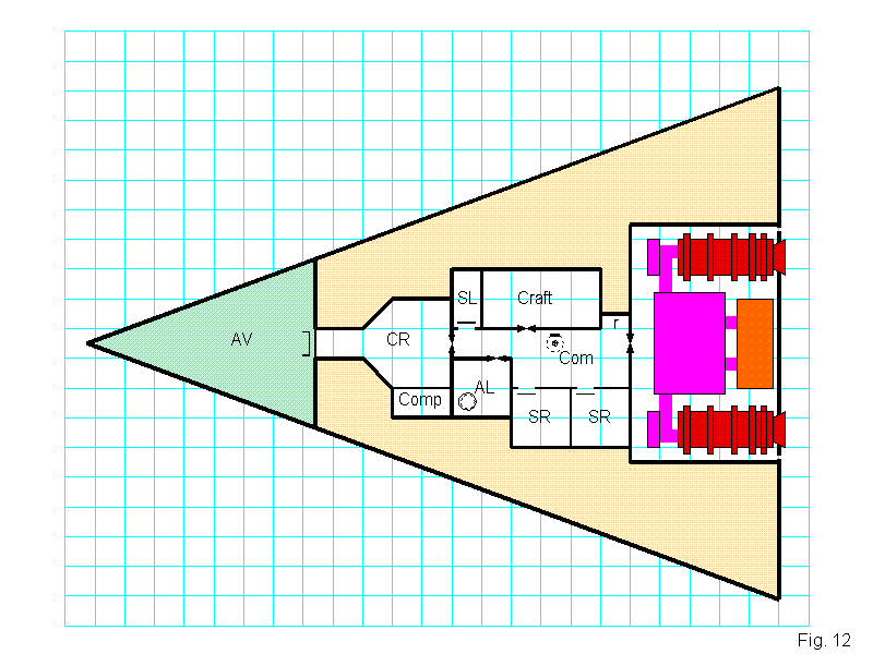
 Reset
the line width to 2". Change the active layer to Doors, Hatches, etc layer
and freeze the Drives layer. Use the Zoom Window command and zoom in to
about one half of the habitation space. Left click on the Iris, Up/down
symbol and place it in the airlock in the corner opposite from the doorway
to the hallway. Select the Iris, wall symbol and place one in the doorway
between the control room and hallway, one in the engineering section doorway
and two in the common area close to the craft and airlock doorways. Use
the Move command and shift key rotate each of the Iris valves 90 degrees
and place one at the craft and airlock doorways. Place a Hatch, Up symbol,
rotated so the hinge is along the wall, in 5' square grid aft of the craft
iris valve in the common area. With snap on draw a 3' long line about 1'
inside the doorway of each stateroom and the ship's locker. Reset the line
width to 1". In an area 1' inside the avionics section from the control
room draw a 4' long line. At the ends of this line draw two 1' long lines
perpendicular to the first extending into the avionics section. (Looks like
a U.) With snap turned off use the Move command and move these lines until
they are centered (1' back) in the doorway between the control room and
the avionics bay. Hide the User 2 layer. Zoom extents. (See Fig 12) (click
on the figure to see it at full size, 800x600)
Reset
the line width to 2". Change the active layer to Doors, Hatches, etc layer
and freeze the Drives layer. Use the Zoom Window command and zoom in to
about one half of the habitation space. Left click on the Iris, Up/down
symbol and place it in the airlock in the corner opposite from the doorway
to the hallway. Select the Iris, wall symbol and place one in the doorway
between the control room and hallway, one in the engineering section doorway
and two in the common area close to the craft and airlock doorways. Use
the Move command and shift key rotate each of the Iris valves 90 degrees
and place one at the craft and airlock doorways. Place a Hatch, Up symbol,
rotated so the hinge is along the wall, in 5' square grid aft of the craft
iris valve in the common area. With snap on draw a 3' long line about 1'
inside the doorway of each stateroom and the ship's locker. Reset the line
width to 1". In an area 1' inside the avionics section from the control
room draw a 4' long line. At the ends of this line draw two 1' long lines
perpendicular to the first extending into the avionics section. (Looks like
a U.) With snap turned off use the Move command and move these lines until
they are centered (1' back) in the doorway between the control room and
the avionics bay. Hide the User 2 layer. Zoom extents. (See Fig 12) (click
on the figure to see it at full size, 800x600) -
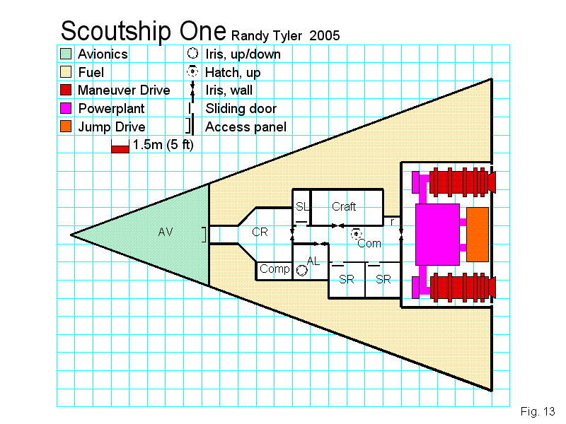
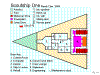
 Make
the active layer Borders and freeze the Doors, Hatches, etc. layer. Reset
the line width to 0". Left click the Text button in the Draw Toolbar, change
the text height to 6'. Type the name of the ship, then paste it close to
the top left corner of the square grid. Change the text height to 3'. Repeat
the text command, type your name and the year then paste it to the right
of the ship name. Selecting each of the colors used in the drawing and the
box command draw a 3' x 3' box in the center of each of the top five 5'
squares along the first, left grid column, under the ship name. Reset the
color to black. Use the text command and give each of the colors a label
identifying it. In the second clear grid column to the right of the 'colors'
text place and/or create the symbols used in the drawing (iris valves, doors,
hatches, access panel). Use the text command and give each a label identifying
it. Create a scale bar with appropriate text under the symbols legend. (See
Fig 13) (click on the figure to see it at full size, 800x600)
Make
the active layer Borders and freeze the Doors, Hatches, etc. layer. Reset
the line width to 0". Left click the Text button in the Draw Toolbar, change
the text height to 6'. Type the name of the ship, then paste it close to
the top left corner of the square grid. Change the text height to 3'. Repeat
the text command, type your name and the year then paste it to the right
of the ship name. Selecting each of the colors used in the drawing and the
box command draw a 3' x 3' box in the center of each of the top five 5'
squares along the first, left grid column, under the ship name. Reset the
color to black. Use the text command and give each of the colors a label
identifying it. In the second clear grid column to the right of the 'colors'
text place and/or create the symbols used in the drawing (iris valves, doors,
hatches, access panel). Use the text command and give each a label identifying
it. Create a scale bar with appropriate text under the symbols legend. (See
Fig 13) (click on the figure to see it at full size, 800x600) -
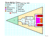
 Change
the active layer to Labels. Make sure the other used layers are frozen.
In addition hide the Drives layer. Erase the abbreviations used and replace
then with bold, 3' 6" numerical text starting with the control room. (Numbers
1 through 9). Before placing the numeral for the engineering space, unhide
the Drives layer so that you can place the number in a clearer spot. Change
the text properties to non-bold and 3' height. Type and place a room key
below and to the left of the drawing. Type a small "r" and place in the
robot alcove between engineering and the air/raft bay. Add the small r to
the room key as "Maintenance robot". Save the deckplan! (See Fig 14) (click
on the figure to see it at full size, 800x600)
Change
the active layer to Labels. Make sure the other used layers are frozen.
In addition hide the Drives layer. Erase the abbreviations used and replace
then with bold, 3' 6" numerical text starting with the control room. (Numbers
1 through 9). Before placing the numeral for the engineering space, unhide
the Drives layer so that you can place the number in a clearer spot. Change
the text properties to non-bold and 3' height. Type and place a room key
below and to the left of the drawing. Type a small "r" and place in the
robot alcove between engineering and the air/raft bay. Add the small r to
the room key as "Maintenance robot". Save the deckplan! (See Fig 14) (click
on the figure to see it at full size, 800x600) -
Congratulations you are finished. You now have an attractive, colorful deckplan to use in the game. You can erase the boxes on User 2 layer if you desire (Hide and freeze all other layers first.). If you return to Section Two you can create more symbols (such as chairs, desk, fresher, bed, etc.) and add them to the Furniture layer. You can use CC2 to draw exterior views if you desire. Hopefully this essay was a help. You can send comments, suggestions and questions about this essay to the author through Freelance Traveller's feedback page
-